online retailer,bulk & wholesale and OEM/ODM e-shop of motor and controller, Shenzhen weigena technology co., LTD")


4 Axis 500KHz Linkage Offline Motion Controller System PLC Control G code+100 Pulse Handwheel MPG with Emergency Stop for CNC Router Engraving Milling Lathe Machine RMHV3.1
About this product
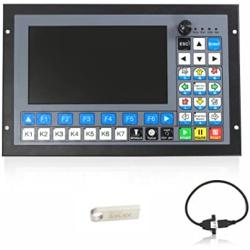
*♞【Brief introduction】The RMHV3.1 is a 4 axis motion controller,the highest uniaxial output pulse is 500KHz and the pulse width can be adjusted.This provides high control precision for stepper motors and servo motors.The operates as a stand alone system without the need of a computer.
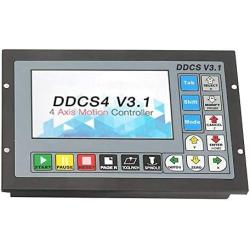
*♞【Compatible with G code set】4.3 inches TFT Screen ; Resolution ratio: 480x272 ; The CNC MOTION SYSTEM Controller can be finished only by 17 keys and it supports the FANUC with high universality to be compatible with G code set.Support the USB flash disk to read the G code,and the size of G codefile has no requirement;
*♞【Brief technical feature】Ordinary digital input interface of 16-circuitoptocoupler coupling isolation;Ordinary digital input interface of 3-circuit optocoupler coupling isolation;Output interface of 0-10V spindle control port with analog quantity (can be modified as PWM output);Support the operation of quickly specify the running position;Support the multi coordinate systems (with automatically saving function in case of power cut);
*♞【Power requirements】The control equipment is 24V-32V DC power input, the current capacity is required not to be lower than 0.5A;(can not lower than DC24V)
*♞【Applications】The RMHV3.1 can be used for many styles and types of CNC machines. Lathes, CNC Routers,Pick&Place and Milling Machine,lathe machine and cutters are just a few examples.
Description
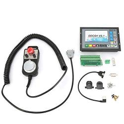
Package:
Package:
Introduction
Introduction
Performance parameter:
Performance parameter:
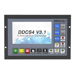
Outward Appearance,Structure and Size
The RMHV2.1 adopts the embedded shell structure, which can punch a square hole on the equipment cabinet and then embed this equipment in the squire hole. Use two locking mechanism from the inside can fix this equipment on the equipment cabinet, with easy installation.
The RMHV2.1 adopts the embedded shell structure, which can punch a square hole on the equipment cabinet and then embed this equipment in the squire hole. Use two locking mechanism from the inside can fix this equipment on the equipment cabinet, with easy installation.
As the picture shows, the wiring section of this controller totally has power interface, USB interface, MPG port, stepper/servo control output interface, spindle control output interface, ESTOP limitprobe and other input interface as well as 6 interfaces with different functions.
As the picture shows, the wiring section of this controller totally has power interface, USB interface, MPG port, stepper/servo control output interface, spindle control output interface, ESTOP limitprobe and other input interface as well as 6 interfaces with different functions.The power interface is 5.08mm wiring terminal. As the picture shows, the right wiring terminal is the positive power, and the left wiring terminal is the negative power, accepting the power supply of 24V-32V DC with direct -current supply. The current capacity is required to be more than 0.5A.
The power interface is 5.08mm wiring terminal. As the picture shows, the right wiring terminal is the positive power, and the left wiring terminal is the negative power, accepting the power supply of 24V-32V DC with direct -current supply. The current capacity is required to be more than 0.5A.This USB Interface is the standard USB socket of A-type, attached a 50cm USB extension cord with installation lugs.
This USB Interface is the standard USB socket of A-type, attached a 50cm USB extension cord with installation lugs.The MPG port picture is showed as the Picture.From the reverse side of the product, it is the 8+9 double raw interface which is close to the USB interface.
The MPG port picture is showed as the Picture.From the reverse side of the product, it is the 8+9 double raw interface which is close to the USB interface.
English abbreviation
English abbreviation
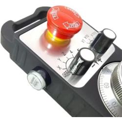
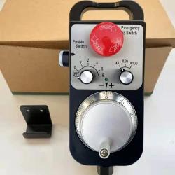
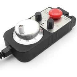
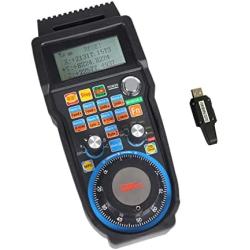
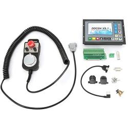
Pendant Handwheel with Emergency stop
x1, x10, x100 switch x1, x10, x100 switch X,Y,Z,4th axis selector switch X,Y,Z,4th axis selector switch LED indicator LED indicator With Emergency stop With Emergency stop High quality professional chassis High quality professional chassis Extendable high quality shielded cable cord Extendable high quality shielded cable cord Magnetic base holder can place anywhere on the machine steel surface Magnetic base holder can place anywhere on the machine steel surface Required 5V+, 150mA, power for MPG Required 5V+, 150mA, power for MPGAll Wiring isolated from MPG unit and provide a easy to install wiring diagram, it suit both commercial machine as a replacement jog control unit or other computer based controller. Which add great control flexibility to the system.
All Wiring isolated from MPG unit and provide a easy to install wiring diagram, it suit both commercial machine as a replacement jog control unit or other computer based controller. Which add great control flexibility to the system.The CNC 4 Axis handheld controller MPG Pendant with x1, x10, x100 selectable.
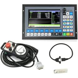
The CNC 4 Axis handheld controller MPG Pendant with x1, x10, x100 selectable. 1 x 100PPR Pendant Handwheel MPG with emergency stop 1 x 4 Axis CNC Offline Motion Controller RMHV3.1 1 x 8GB USB Flash drive 1 x USB Extension Cable PDF. English user manual RMHV3.1 is the 4 axis motion controller which has been researched and developed for four years. The control period of each position is only 4 milliseconds, with a high control precision. The highest uniaxial output pulse is 500KHz and the pulse width can be adjusted. It supports the common stepper motor and servo motor. RMHV3.1 numerical control system adopts the ARM+FPGA design framework. The ARM can finish the part of human-computer interface and code analysis and the FPGA can finish the part of underlying algorithm and control pulse generate, with the reasonable design, reliable control and easy operation. The panel layout structure of RMHV3.1 is rational. The CNC MOTION SYSTEM Controller can be finished only by 17 keys and it supports the FANUC with high universality to be compatible with G code set. Our user manual introduces the operation method of the RMHV3.1,the machine tool and the operation procedure of the machine tool. By lots of graphical representation and examples, the uses can quickly learn to use the RMHV3.1 CNC system. Ordinary digital input interface of 16-circuitoptocoupler coupling isolation Ordinary digital input interface of 3-circuit optocoupler coupling isolation Output interface of 0-10V spindle control port with analog quantity(can be modified as PWM output); Support the 4 axis stepper motor control, the highest control pulse output of single axis is 500KHz; ARM9 main control chip; FPGA core algorithm chip; 4.3 inches TFT screen, resolution ratio: 480*272; 17 operational keys; The control equipment is 24V-32V DC power input, the current capacity is required not to be lower than 0.5A;(can not lower than DC24V) Support the USB flash disk to read the G code,and the size of G codefile has no requirement; Be equipped with MPG port and support digital display MPG as well as support the general MPG in the market. Support the panel key with single-axis manual operation, manual step and CONToperation; Support the operation of quickly specify the running position; Support the multi coordinate systems (with automatically saving function in case of power cut); Support the function of saving data automatically after power down (press the start to automatically save the data in the operation, automatically save the data after power down) The panel size of the product is 163mm*102mm*5mm; The size of main body is 156mm*93mm*45mm; The size of square hole installed on the equipment cabinet is 156mm*93mm. The interface of third group from the right side is the spindle control output interface. In the spindle control output interface, the start and stop of spindle (M3/M5), cooling liquid (M8/M9), lubricating oil (M10/M11)Â’s three output terminals are totally the signal of open ground. The highestelectric current can be absorbed is 20mA. The speeding governing output terminal can output 0-10V adjustable voltage. It can adjust the speed of spindle motor by adjusting the F value of spindle and outputting to the frequency converter. can control the VFD,frequency conversion spindle only needs 2 signals and one is the start-stop control and the other is speed control/Speeding governing output (0-10V) the interface of group one from the lift side is the ESTOP probe input interface This interface contains three kinds of input signals, including the external-expansion start and stop, probe and limit/home. FRO: the FRO mainly refers to adjust the FRO value to amend the current feed rate under the situation that the F value has been confirmed before the processing course or in the processing course. The actual rate F#=setting rate F*FRO. SRO: the SROrate mainly refers to adjust the SROrate to amend the current speed of spindle under the situation that the S value has been confirmed before the processing course or in the processing course. The actual speed of spindleS#=setting rate S* SRO. SRJ: SRJ, under the situation that the defaultvalue ofmanual operation rate has been set, it is impossible to set the value again to amend the manual operation rate when it is required to adjust the manual operation speed and CONToperation speed. At this moment, the SRJ value can be modified to realize the purpose of amending the manual operation speed. The actual speed of manual operation FS#=setting manual operation speed SRJ*. F: Feed rate, the unit is mm/min. For example F=2000, indicates that it can feed 2000mm per minute; S: speed of spindle, the unit is rad/min. For example S=20000,indicates that it can rotate 20000 per minute; X: The coordinate code of X axis. Y: The coordinate code of Y axis. Z: The coordinate code of Z axis. A: The coordinate code of A axis Busy: Server busy, it cannot conduct the processing operation, and parts of the function are open. For example, amend the FRO and value of SRO. REDAY: REDAY mode, any operation can be done at this time,including the processing or modifying the parameter or starting the 2nd mode Reset: reset mode, all the operations are forbidden to do at this time. CONT:continuous operation, each axis can conduct the CONT operation under this mode. Step:Manual step mode?each axis can conduct the manual step operation under this mode MPG: MPGMode, each axis can conduct the MPG operation under this mode AUTO: Automatic processing mode, it will show AUTO when enters the state of automatic processing. x1, x10, x100 switch X,Y,Z,4th axis selector switch LED indicator With Emergency stop High quality professional chassis Extendable high quality shielded cable cord Magnetic base holder can place anywhere on the machine steel surface Required 5V+, 150mA, power for MPG Resolution:100PPR Supply Voltage:DC5V +/-5% Supply Current:?80mA Output Voltage:?2.5V and ?0.4V Output Current:<40mA Fall/Rise time:?5ns(typ) Switch:X1,X10,X100 Axis Switch:OFF,X,Y,Z,4 Response Frequency:0-10KHzFrequency Asked Questions
What is motormaker.net?
MotorMaker.net is an online retailer and bulk order e-shop for electric motor and controller products, range from standard products and customized products. Main production bases are located in Shenzhen, Dongguan, Wuhan, Shanghai and Chengdu. A professional team supports your order and customization design.
What service can be supported from motormaker.net?
MotorMaker.net offer product order and product customization service. All orders will be supported after-sales service, including quanlity gurantee, and technical support.
How to order products from motormaker.net?
You can online order product from motormaker.net by adding product to cart and got to checkout page. Multiple currency options are supported. You can choose suitable currency to place order. Before checkout, you should register account to submit order information.
How to delivery your order from motormaker.net to you?
For order delivery, motormaker.net provides three shipping options, express, air-flight and sea freight. You can choose one option according to your order.
How to inquiry product bulk price?
For the interested product, you can submit bulk price inquiry by bulk order inquiry form.
Related Products