online retailer,bulk & wholesale and OEM/ODM e-shop of motor and controller, Shenzhen weigena technology co., LTD")


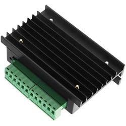
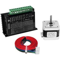
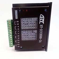
OUYZGIA TB6600 Stepper Motor Drivers 4A Stepper Driver Controller for Nema 17, 23 and 34 Stepper Motor 32 Segments for 42 57 86 Stepper Motor Drivers, Upgraded Version-2PCS
About this product
*Signal Input: Single-ended, pulse/direction. Optocoupler isolated signal input, strong anti-interference capability
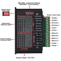
*Subdivision Options: 1/2/4/8/16/32 subdivision to drive 4/6/8 wire 2 phase/4 phase hybrid stepper motors, (current less than or equal to 4.0A). Compatible with stepper motors with step angles of 1.8° and 0.9°
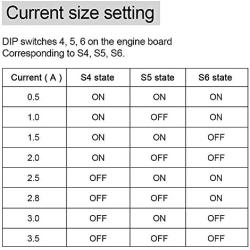
*Current and Voltage: Output Current: 0.5A-4.0A, the maximum output current is 4.0A. Input voltage: 9-42VDC, external signal 3.3-24V can be connected directly without series resistor
*Safe and Reliable: Overheat, overcurrent, undervoltage lockout, input voltage protection against reversal, etc. Safer. The current is automatically halved at standstill
*High Compatibility: Suitable for all brands of 4/6/8 wire 2/4 phase hybrid stepper motors. Suitable for various small and medium-sized automation equipment and instruments, such as: engraving machines, marking machines, cutting machines, laser illumination, plotters, CNC machine tools etc
Description
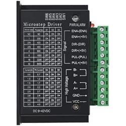
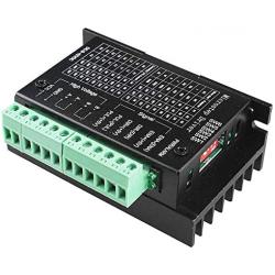
Description of input and output interfaces:
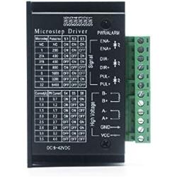
PUL+: Step Pulse signal + , PUL- : Step Pulse signal -
DIR+: Motor Direction control Signal+, DIR-: Motor Direction control Signal-
EN+: Motor enable signal+, EN-: Motor enable signal-
A+: Connects motor winding phase A+,
A-: Connects motor winding A- phase.
B+: Connection to motor winding B+ phase,
B-: Connection to motor winding B- phase.
VCC: Power +, GND: Power -
1. There are three input signals, they are: Step pulse signal PUL+, PUL-; Direction level signal DIR+, DIR- Offline signal EN+, EN-. There are two connection methods for the input signal interface. Users can use common anode connection or common cathode connection according to their needs.
The ENA terminal does not need to be connected. When the ENA is activated, the motor rotor is free (offline). At this point, you can manually rotate the motor shaft to make the adjustment that suits you. After the manual adjustment is complete, set the ENA to the inactive state and continue with the automatic control.
connect PUL+, DIR+, EN+ to the control system power supply respectively. If the power supply is +5V then it can be connected directly, if the power supply is greater than +5V, then an external current limiting resistor R If this power supply is greater than +5V, an external current limiting resistor R must be added to ensure that 8-15mA of drive current is supplied to the driver's internal optical coupler. The pulse input signal is connected via CP- The pulse input signal is connected via CP-, the direction signal is connected via DIR- and the enable signal is connected via EN-.
connect PUL-, DIR-, EN- to the ground of the control system respectively; pulse output The incoming signal is connected through PUL+, the direction signal is connected through DIR+, and the enable signal is connected through EN+. If a current-limiting resistor is required, the connection method of the current-limiting resistor R is the same as the common anode connection.
Frequency Asked Questions
What is motormaker.net?
MotorMaker.net is an online retailer and bulk order e-shop for electric motor and controller products, range from standard products and customized products. Main production bases are located in Shenzhen, Dongguan, Wuhan, Shanghai and Chengdu. A professional team supports your order and customization design.
What service can be supported from motormaker.net?
MotorMaker.net offer product order and product customization service. All orders will be supported after-sales service, including quanlity gurantee, and technical support.
How to order products from motormaker.net?
You can online order product from motormaker.net by adding product to cart and got to checkout page. Multiple currency options are supported. You can choose suitable currency to place order. Before checkout, you should register account to submit order information.
How to delivery your order from motormaker.net to you?
For order delivery, motormaker.net provides three shipping options, express, air-flight and sea freight. You can choose one option according to your order.
How to inquiry product bulk price?
For the interested product, you can submit bulk price inquiry by bulk order inquiry form.
Related Products