online retailer,bulk & wholesale and OEM/ODM e-shop of motor and controller, Shenzhen weigena technology co., LTD")


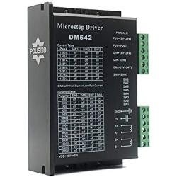
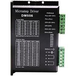
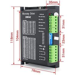
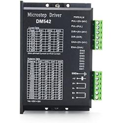
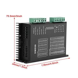
DM542 3D Printer CNC Microstep Driver Stepper Motor Controller 2-Phase Digital Stepper Motor Driver 20-50V DC Max 4.2A for Nema 17, Nema 23 Stepper Motor
Product Code: MM3774
Availability: Pre-Order, Inquiry Price
About this product
*Package include:1 pcs DM542 stepper motor driver
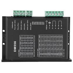
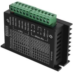
*Specification:input voltage:20-50VDC,out current:1-4.2A,MAX power:200w,subdivision:2/4/8/16/32/64128/5/10/20/25/40/50/100/125,temperature:-10-50°C
*application:suit for Nema 17, Nema 23 and Nema34 Stepper Motor,2-phase hybrid stepper motors (Outer diameter: 42, 57,86mm).
*Product features:Strong anti-interference ability. With over current protection and over-voltage protection
Description
1. Electrical parameters: Input voltage: DC 24?50V input Output current: less than 4 amperes Output current: 1.0A?4.2A Power consumption: power consumption: 80W; internal insurance: 6A Temperature: working temperature -10?50?; storage temperature -40??70? Humidity: no condensation, no water droplets Gas: non-flammable gas and conductive dust Weight: 250 grams 2. Control signal interface: 1. Definition of control signal PLS+: Step pulse signal input positive terminal or positive step pulse signal input positive terminal PLS-: Step pulse signal input negative terminal or positive step pulse signal input negative terminal DIR+: Step direction signal input positive terminal or reverse step pulse signal input positive terminal DIR-: Step direction signal input negative terminal or reverse step pulse signal input negative terminal ENA+: Offline enable reset signal input positive terminal ENA-: Offline enable reset signal input negative terminal When the offline enable signal is valid, the drive fault is reset, any valid pulse is prohibited, the output power element of the drive is turned off, and the motor has no holding torque 2. Control signal connection The control signal of the host computer can be effective at high level or at low level. When high is effective, connect the negative ends of all control signals together as the signal ground, when low, connect the positive ends of all control signals together as the signal common end. Now take the open collector and PNP output as an example, the interface circuit diagram is as follows: Drive wiring: A complete stepper motor control system should contain stepper drives, DC power supplies and controllers (pulse sources). The following is a typical system wiring diagram:
Frequency Asked Questions
What is motormaker.net?
MotorMaker.net is an online retailer and bulk order e-shop for electric motor and controller products, range from standard products and customized products. Main production bases are located in Shenzhen, Dongguan, Wuhan, Shanghai and Chengdu. A professional team supports your order and customization design.
What service can be supported from motormaker.net?
MotorMaker.net offer product order and product customization service. All orders will be supported after-sales service, including quanlity gurantee, and technical support.
How to order products from motormaker.net?
You can online order product from motormaker.net by adding product to cart and got to checkout page. Multiple currency options are supported. You can choose suitable currency to place order. Before checkout, you should register account to submit order information.
How to delivery your order from motormaker.net to you?
For order delivery, motormaker.net provides three shipping options, express, air-flight and sea freight. You can choose one option according to your order.
How to inquiry product bulk price?
For the interested product, you can submit bulk price inquiry by bulk order inquiry form.
Related Products